MPPT Solar Charge Controller Circuit Diagram | Complete Guide
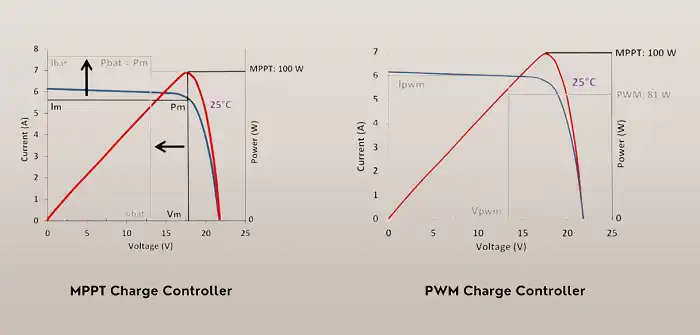
The MPPT controller operates on a simple yet powerful principle. It continuously adjusts the electrical operating point of solar panels to extract the maximum possible power, regardless of fluctuating environmental conditions. This adaptive approach results in significantly higher efficiency compared to traditional Pulse Width Modulation (PWM) controllers, especially in scenarios where the solar panel voltage substantially exceeds the battery voltage.
Advantages of Using MPPT Charge Controller
The advantages of incorporating an MPPT controller into a solar power system are manifold. Users typically experience an energy harvest increase of 20-30% compared to systems using PWM controllers. This boost in efficiency translates to more power available for use or storage.
Additionally, MPPT controllers offer the flexibility to use higher voltage solar panels with lower voltage batteries, a feature particularly useful in certain system designs. The optimized charging process facilitated by MPPT controllers also contributes to improved battery life.
Furthermore, these controllers exhibit superior performance in challenging conditions such as cold weather or partial panel shading, making them versatile across various environments.
How MPPT Circuit Controller Works
Controller Body
MPPT controller can be broken down into four primary sections: the input section, MPPT control unit, power conversion stage, and output section.
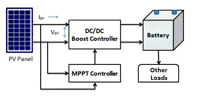
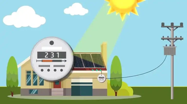
The input section serves as the interface between the solar panels and the controller. It typically includes protection circuitry to safeguard against voltage spikes and reverse polarity. The MPPT control unit houses the microcontroller, which is responsible for implementing the MPPT algorithm.
The power conversion stage contains the DC-DC converter. This stage is responsible for adjusting the voltage and current levels to match the optimal operating point determined by the control unit. Finally, the output section connects to the battery and includes charge control circuitry to ensure safe and efficient battery charging.
Controller Algorithm
At the heart of every MPPT controller lies its algorithm. The most prevalent MPPT algorithms include Perturb and Observe (P&O), Incremental Conductance, Fractional Open-Circuit Voltage, and Fractional Short-Circuit Current. Each of these algorithms approaches the task of finding the maximum power point differently, with varying levels of accuracy, speed, and complexity.
The P&O method, for instance, works by making small adjustments to the operating voltage and observing the resulting change in power output. If the power increases, the algorithm continues to adjust the voltage in the same direction; if it decreases, the direction is reversed. This process continues indefinitely, allowing the system to track the maximum power point as conditions change.
The power stage of an MPPT controller typically employs one of three converter types: buck, boost, or buck-boost (which includes SEPIC converters). Buck converters are efficient when the panel voltage is consistently higher than the battery voltage. Boost converters come into play when the panel voltage can dip below the battery voltage. Buck-boost or SEPIC converters offer the most flexibility, able to handle a wide range of voltage relationships, albeit with a slight efficiency trade-off.
Sample Circuit Diagrams for MPPT Charge Controller
To better understand the practical implementation of MPPT controllers, let’s examine two types of circuits: one based on a dedicated MPPT IC and another using an Arduino for control.
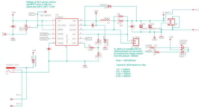
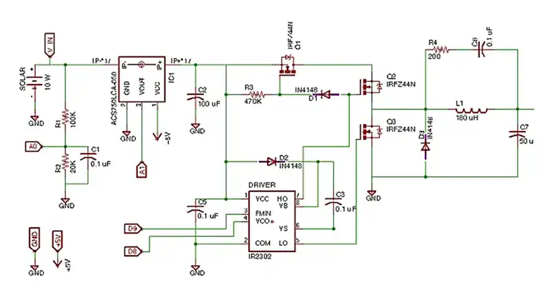
The dedicated MPPT IC-based controller utilizes a specialized integrated circuit designed specifically for MPPT control. These ICs often come packed with features such as integrated MOSFET drivers, built-in current sensing capabilities, temperature compensation, and multiple charging modes. The external components in this circuit are carefully chosen based on the desired input voltage range, output current, and battery specifications. This approach offers a compact and efficient solution, ideal for commercial or high-reliability applications.
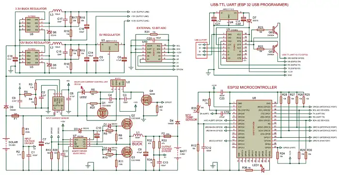
In contrast, the Arduino-based MPPT controller represents a more DIY-friendly approach, perfect for learning and experimentation. This circuit typically includes an Arduino board (such as an Arduino Uno) as the control center. Voltage dividers are used to measure panel and battery voltages, while a current sensor (like the ACS712) monitors the current flow. A MOSFET driver (e.g., IR2104) interfaces between the low-power Arduino and the high-power MOSFET that controls the DC-DC converter. The power stage consists of the MOSFET, a freewheeling diode, an inductor, and capacitors.
In this setup, the Arduino continuously reads the voltage and current sensors, calculates the optimal operating point using the implemented MPPT algorithm, and adjusts the PWM duty cycle to control the DC-DC converter accordingly. This approach offers easy modification and experimentation with different MPPT algorithms and control strategies.
How to Build Your Own MPPT Controller
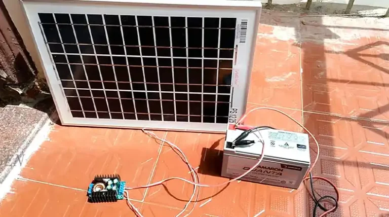
Building a DIY MPPT controller can be rewarding but requires caution due to high voltages involved. Here’s a step-by-step overview:
- Define System Requirements: Determine the input voltage range from your solar panels, desired output current, and battery specifications. These parameters will guide all subsequent decisions.
- Choose Control Method: Select between a dedicated MPPT IC or a microcontroller-based approach. Dedicated ICs offer simplicity, while microcontrollers provide flexibility for customization.
- Select DC-DC Converter Topology: Based on your input and output voltage relationship, choose between buck (step-down), boost (step-up), or buck-boost configurations. This choice affects efficiency and complexity.
- Component Selection: Carefully choose power MOSFETs, inductors, capacitors, and other semiconductor devices. Ensure voltage and current ratings exceed your system requirements with appropriate safety margins.
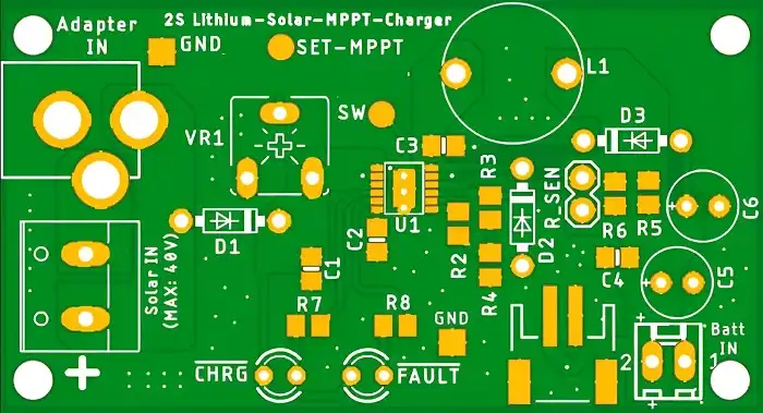
- PCB Layout Design: Design your PCB with careful consideration of high-current paths and thermal management. Use appropriate trace widths and consider multi-layer PCBs to separate power and control circuits.
- Circuit Assembly: Begin assembly with the low-voltage control sections before incorporating power components. This approach facilitates easier troubleshooting and protects sensitive components.
- Testing and Calibration: Start testing at low power levels, gradually increasing to full capacity. Conduct comprehensive tests under various conditions to identify potential issues or areas for improvement.
- Safety Measures: Implement proper isolation, overcurrent protection, and heat dissipation strategies. Ensure your workspace is properly equipped for high-voltage work.
- Documentation: Keep detailed records of your design choices, component specifications, and test results for future reference or troubleshooting.
Remember, while this process can be enlightening, it carries inherent risks. Always prioritize safety, and for critical applications, consider using commercially available controllers. Approach each step with caution and patience, and don’t hesitate to seek expert advice when needed.