What is Negative Grounding in a Solar Inverter? A Complete Guide
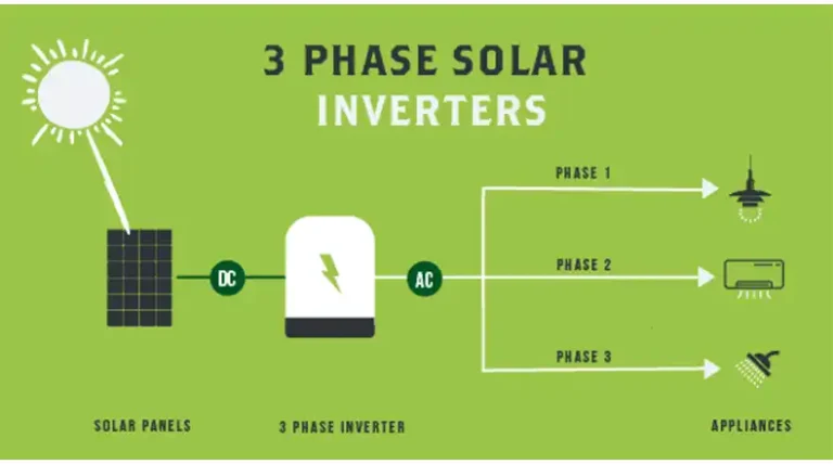
At the heart of every solar system, lies the solar inverter, a crucial component that converts the direct current (DC) generated by solar panels into alternating current (AC) for use in homes and businesses. While the inverter plays a vital role in the overall functionality of the solar system, proper grounding is equally important for ensuring safety, stability, and optimal performance.
Grounding is the process of connecting an electrical system to the earth, providing a low-resistance path for fault currents and dissipating electrical charges. In the context of solar inverters, negative grounding is a specific grounding method that involves connecting the negative terminal of the system to the earth’s ground. This practice is widely adopted due to its numerous benefits and is often mandated by local regulations and building codes.
Different Types of Grounding
Before delving into negative grounding, it’s essential to understand the fundamentals of grounding systems. Grounding can be classified into two main categories: equipment grounding and system grounding.
Equipment Grounding: This type of grounding involves connecting the non-current-carrying metal parts of electrical equipment to the earth ground. Its primary purpose is to provide a low-resistance path for fault currents, preventing the metal enclosures from becoming energized and posing a risk of electric shock.
System Grounding: System grounding refers to the intentional connection of one of the current-carrying conductors to the earth ground. This practice is employed to establish a reference point for the electrical system and facilitate fault detection and protection. System grounding can be further divided into three subcategories:
- Positive Grounding: In this method, the positive terminal of the system is connected to the earth ground. While positive grounding is sometimes used in certain applications, it is generally not recommended for solar inverters due to potential disadvantages, such as increased risk of corrosion and surface polarization.
- Negative Grounding: As mentioned earlier, negative grounding involves connecting the negative terminal of the system to the earth ground. This method is widely adopted in solar inverter systems and offers numerous benefits, which will be discussed in detail later.
- Ungrounded Systems: In ungrounded systems, neither the positive nor the negative terminal is intentionally connected to the earth ground. While this approach may be used in specific situations, it is generally not recommended for solar inverter systems due to safety concerns and potential issues with fault detection.
What is Negative Grounding?
Negative grounding, also known as negative system grounding, is the practice of intentionally connecting the negative terminal of a solar inverter system to the earth’s ground. This connection is established through a low-resistance grounding conductor, typically made of copper, and a grounding electrode, such as a ground rod or a grounding ring
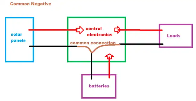
A Typical Negative Grounding Diagram
The primary purpose of negative grounding is to provide a reference point for the electrical system and a safe path for fault currents to dissipate into the earth. By connecting the negative terminal to the ground, any voltage imbalances or fault currents can be safely directed to the earth, preventing potential hazards and damage to equipment.
Compared to positive grounding, negative grounding is generally preferred for solar inverter systems due to its inherent advantages. Positive grounding can lead to issues such as increased corrosion and surface polarization, which can compromise the system’s performance and longevity.
Benefits of Negative Grounding
Implementing negative grounding in solar inverter systems offers several significant benefits, including:
Safety
- Reducing Electric Shock Risk: By providing a low-resistance path to the earth, negative grounding minimizes the risk of electric shocks to personnel working on or near the system. Any fault currents or voltage imbalances are safely dissipated into the ground, preventing potentially dangerous situations.
- Protecting Against Fault Currents: In the event of a fault or short circuit, negative grounding ensures that fault currents are safely directed to the earth, protecting equipment and personnel from damage or injury.
Voltage Control and Surge Protection
- Preventing Voltage Buildup: Negative grounding helps prevent the buildup of potentially harmful voltage levels within the system by providing a reference point and a path for excess charges to dissipate into the ground.
- Providing Lightning Strike Path: During lightning strikes or other surge events, negative grounding offers a low-resistance path for the surge current to flow into the earth, helping to protect the system components from damage.
System Performance and Efficiency
- Reduced Electrical Noise and Interference: By establishing a stable reference point, negative grounding can minimize electrical noise and interference, resulting in improved power quality and system efficiency.
- Enhanced Fault Detection: Negative grounding facilitates the detection of ground faults, enabling timely troubleshooting and maintenance, which can help maintain optimal system performance.
How Solar Negative Grounding Works
The basic principle behind negative grounding is to intentionally connect the negative side of the solar system’s electrical circuit to the earth (ground). This connection is made through a grounding conductor (usually a copper wire) and a grounding electrode, which is a metal rod or plate driven into the earth.
Picture the solar panels as a source of electrical current, like a battery. The positive side connects to the inverter, while the negative side needs to connect back to the “other terminal” of the battery to complete the circuit. In this case, the earth itself acts as that “other terminal.”
By connecting the negative side to the ground, you create a safe escape path for any stray electrical currents or voltage buildup. It’s like giving those excess electrons a way to harmlessly flow into the earth, rather than remaining in the circuit where they could potentially cause shocks or damage equipment.
The grounding conductor acts as a highway, allowing those excess currents an easy path to flow from the negative side of the circuit down into the earth through the grounding electrode embedded in the soil. The grounding electrode disperses those currents safely into the surrounding soil.
The Difference Between Negative and Positive Grounding
While negative grounding is the most common and recommended practice for solar inverter systems, it’s important to understand the alternative approach: positive grounding.
In a positive grounding system, instead of the negative terminal, it is the positive terminal of the solar array that is intentionally connected to the earth ground through the grounding conductor and electrode.
Positive grounding is sometimes used in certain applications, but it is generally not recommended for solar inverter systems due to several potential disadvantages:
- Increased risk of corrosion: Connecting the positive terminal to the earth ground can accelerate corrosion in the grounding components and system equipment.
- Surface polarization: Positive grounding can lead to surface polarization effects, which can degrade system performance over time.
- Safety concerns: In the event of a ground fault, a positive grounding system may not provide the same level of protection as a negative grounding system.
For these reasons, negative grounding is the preferred and more widely adopted grounding method for solar inverter installations.
Determining Your Grounding Type
If you are unsure whether your solar inverter system is using negative or positive grounding, there are a few ways to determine the grounding type:
- Check the system documentation and specifications provided by the manufacturer or installer. This should clearly indicate the grounding configuration.
- Visually inspect the grounding connections at the inverter. The grounding conductor should be connected to either the negative or positive terminal of the inverter or array.
- Use a multimeter to test for continuity between the grounding conductor and the negative or positive terminal. The terminal with continuity to the grounding conductor is the grounded terminal.
- Consult a qualified solar professional or electrician. They can perform the necessary inspections and tests to identify the grounding type accurately.
It’s crucial to determine the grounding type before attempting any modifications or maintenance on the grounding system, as improper handling could lead to safety risks or system damage.
End Notes
Negative grounding plays a crucial role in ensuring the safe and reliable operation of solar inverter systems. By connecting the negative terminal to the earth ground, negative grounding provides a reference point, dissipates fault currents, and mitigates potential hazards.
The benefits of negative grounding, including enhanced safety, voltage control, surge protection, and improved system performance, make it a widely adopted practice in the solar industry. However, proper installation, maintenance, and adherence to codes and regulations are essential to realize these benefits fully.
FAQs
Can positive grounding be used instead of negative grounding in solar inverter systems?
While positive grounding is sometimes used in certain applications, it is generally not recommended for solar inverter systems due to potential disadvantages, such as increased risk of corrosion and surface polarization. Negative grounding is the preferred method for solar inverters due to its inherent advantages and industry-wide adoption.
Is it necessary to have a separate grounding system for the solar inverter, or can it be connected to the existing building ground?
In many cases, the solar inverter grounding system can be connected to the existing building ground, provided that the building ground meets the necessary requirements and has sufficient capacity to handle potential fault currents from the solar system. However, it is essential to consult local codes and regulations, as well as professional electricians or solar installers, to ensure compliance and proper integration.
How often should the grounding system be inspected and maintained?
The frequency of inspections and maintenance for the grounding system may vary depending on local conditions, system age, and manufacturer recommendations. As a general guideline, it is recommended to perform visual inspections at least annually and more comprehensive checks every 3-5 years or as specified by the equipment manufacturer or local regulations.
Can lightning strikes damage a properly grounded solar inverter system?
While a properly designed and installed grounding system can provide a low-resistance path for lightning strike currents to dissipate into the earth, direct lightning strikes can still potentially cause damage to system components. However, an effective grounding system can significantly reduce the risk of severe damage and help protect personnel and equipment.
What should be done if a ground fault is detected in the solar inverter system?
If a ground fault is detected, it is crucial to take prompt action to identify and address the issue. This may involve shutting down the system, inspecting the grounding system and components for any visible issues, and consulting professionals or equipment manufacturers for further troubleshooting and repair guidance. Continuing to operate with a ground fault can pose safety risks and potentially lead to further damage.