How to Make Solar Emergency Light at Home?
Finding yourself suddenly enveloped in darkness during a power outage can be disorienting and unsafe. Rather than relying on old-school flashlights or candles, a DIY solar-charged emergency light offers a reliable hands-free illumination solution. In short, by creatively combining easily available electronic components like solar panels, LEDs, batteries, and charging modules, you can build a custom emergency lighting system that automatically activates when it goes dark. With basic electronic skills and tools, the project can be tackled over a weekend for around $50 while judiciously reusing household items. So if you seek some weekend hobbying and valuable backup lighting for home emergencies, constructing an automated solar-powered lamp from scratch ticks all boxes!
What Procedure I Follow for Making the Light Professionally
For those comfortable working with electronics, here is how to construct a robust solar emergency light with professional-grade parts:
6V SLA Battery: This battery stores the electrical energy generated by the solar panel.
LED Strip: This component provides the light source for the emergency light.
Regulator IC LM317: This integrated circuit regulates the voltage from the battery to a stable 5V for the LED strip.
Transistor: BD140: This transistor acts as a switch, controlling the flow of current to the LED strip.
Transistor BC547: This transistor amplifies the signal from the LM317 to activate the BD140 transistor.
Diode-1N4007: This diode protects the circuit from reverse current damage.
Zenner Diode: This diode limits the voltage to the LM317 to prevent damage.
Resistor-330Ω: This resistor limits the current to the base of the BC547 transistor.
Resistor-1kΩ: This resistor sets the current limit for the LED strip.
Resistor-5R/2W: This resistor provides additional current limiting for the LED strip.
Capacitor-1000uF: This capacitor filters out any noise or spikes in the power supply.
Capacitor-0.1uF: This capacitor ensures stability in the voltage regulation circuit.
LED-5mm: This LED serves as an indicator light, showing whether the battery is charging or discharging.
Screw Terminals: These terminals provide easy connections for the wires.
Heat Sink: This component helps dissipate heat generated by the LM317 regulator.
24AWG Wires: These wires are used for connecting the various components.
Perforated Board: This board provides a mounting base for the components.
Soldering Iron: This tool is used to join the components together using solder.
Multimeter: This tool measures voltage, current, and resistance to ensure proper circuit operation.
Wire Stripper: This tool removes the insulation from the ends of wires.
Nose Plier: This tool is used to bend and manipulate wires.
Steps for Making Solar Emergency Lights at Home
Step 1 – Assembling the Circuit
>Mount the LM317 regulator on the perforated board.
>Attach the resistors, capacitors, and diodes to the LM317 regulator according to the circuit diagram.
>Connect the transistors to the remaining components based on the circuit diagram.
Solder the connections securely.
Step 2 – Connecting the LED Strip
>Connect the positive terminal of the LED strip to the output of the LM317 regulator.
>Connect the negative terminal of the LED strip to the ground connection on the circuit board.
Step 3 – Connecting the Battery
>Connect the positive terminal of the battery to the input of the LM317 regulator.
>Connect the negative terminal of the battery to the ground connection on the circuit board.
Step 4 – Testing the Circuit:
>Connect a DC power supply to the input of the circuit board.
>Adjust the voltage of the power supply to 6V.
>The LED strip should illuminate.
Step 5 – Enclosing the Circuit:
>Place the circuit board inside a suitable enclosure.
>Mount the LED strip in a visible location on the enclosure.
>Install a switch to control the LED strip.
Step 6 – Connecting the Solar Panel
>Connect the positive terminal of the solar panel to the input of the circuit board.
>Connect the negative terminal of the solar panel to the ground connection on the circuit board.
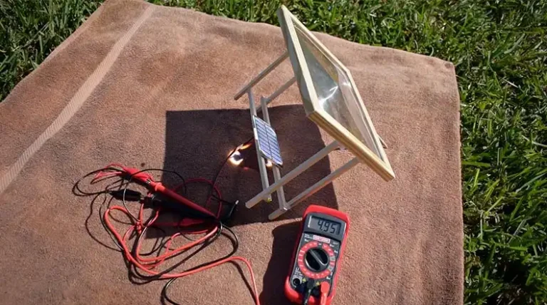
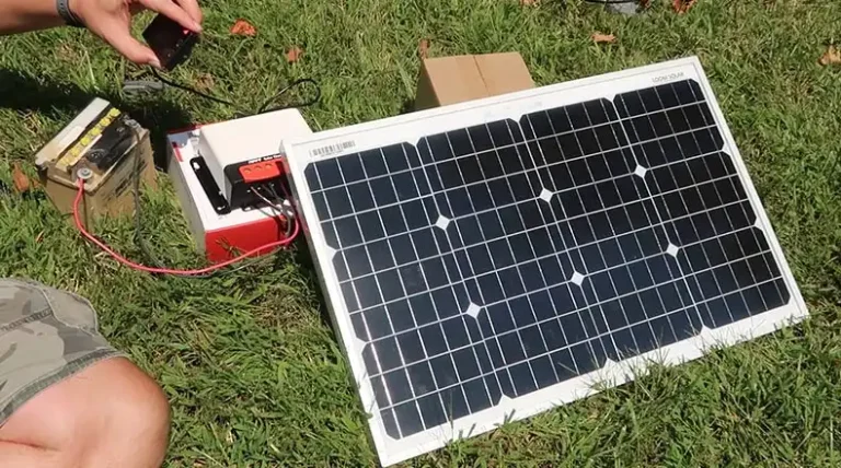
Step 7 – Testing the Solar Charging System
>Expose the solar panel to sunlight.
>The LED indicator light should illuminate, indicating that the battery is charging.
Step 8 – Final Touches
>Secure the enclosure and ensure that all connections are properly insulated.
>Attach a handle or mounting bracket to the enclosure for easy carrying or installation.
Your DIY solar emergency light is now ready for use. You can use it during power outages or as a backup light source for camping or other outdoor activities.
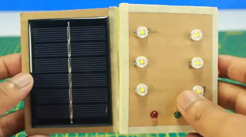
Procedure for Making the Light in an Easy Way
Here is how you can build a simpler solar-powered light with everyday components:
Materials
- 18650 Li-ion 3.7v battery
- 5v solar panel
- TP4056 Charger
- 3.7v COB led
- Switch
- PVC sheet
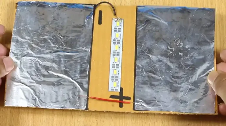
Steps for Making
Step 1 – Cut the PVC sheet to size
You will need a piece of PVC sheet that is large enough to fit the battery, solar panel, TP4056 charger, switch, and LED.
Step 2 – Glue the components to the PVC sheet
Use a strong glue to glue the battery, solar panel, TP4056 charger, switch, and LED to the PVC sheet.
Step 3 – Wire the components together
Connect the positive terminal of the battery to the positive terminal of the TP4056 charger. Connect the negative terminal of the battery to the negative terminal of the TP4056 charger. Connect the output of the TP4056 charger to the positive terminal of the LED. Connect the negative terminal of the LED to the switch. Connect the switch to the negative terminal of the battery.
Step 4 – Test the light
Once you have wired the components together, test the light to make sure that it works.
Advanced Version With Dual Mode Operation
For greater flexibility, the basic solar emergency light circuit can be upgraded to add dual operation modes:
- Auto-on when surroundings dark
- Manual on/off control via an external switch
Additional Parts & Tools Needed
- Latching push button switch
- IC 555 timer and associated resistors/capacitors
- Soldering equipment
- Electronics know-how for circuit assembly
Working Principle
The 555 timer IC-based circuit allows the LED lights to switch on either automatically based on charging/ambient light thresholds or manually toggle on/off with a button press. This dual control mode allows the use of the lighting fixture as both an automated emergency bulb and a portable manual torch. Consult electronic circuit guides for details of wiring this slightly complex but very adaptable improvised solar lighting.
How Much It Will Cost to Make the Emergency Solar Light?
For the Simple Solar Emergency Light using a basic LED strip, 3.7V battery, and charging module, materials would cost around $30 to $50. Breakdown:
- 5V Mini Solar Panel – $10
- 18650 battery – $6
- TP4056 Charger – $3
- LED strip (1 meter) – $6
- Enclosure, wires, switches, misc. – $5 to $20
For Scaling Up to Room-level Lighting using higher capacity panels, batteries, and multiple COB LEDs, the budget would be:
- 10 to 20W solar panel – $50 to $100
- Two 12V 7Ah SLA batteries – $60
- LED COB lights x 4 – $40
- Enclosure, wiring – $30
Total: Around $180 to $230
Additionally a soldering iron, glue gun, cutter/pliers could be another $30 if working from scratch.
So realistically, starting from scratch expect a budget of $50 for a basic panel, $100 to $150 for more heavy-duty emergency room lighting that runs for hours.
![[Explained] What Size Fuse for 3000 Watt Amp for Solar Inverter?](https://www.itekenergy.com/wp-content/uploads/2023/08/What-Size-Fuse-for-3000-Watt-Amp-for-Solar-Inverter-768x428.webp)